
Tank project
INTRODUCTION
The tank project
This project was developed in collaboration with my wife during her PhD in Computational Neuroscience at the University of Birmingham (UK). The objective was to create an instrument which would deliver moving tactile stimuli using the translation of a pad. This page describes how the project was executed.
Functional overview
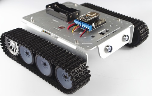
The tank is constructed of a wooden structure which supports 2 plastic chains.

The plastic chains are moved by 2 indipendent motors. The movement is controlled by an Arduino board:
The whole structure is supported by a table and covered by a black cloth:

Technical overview
The current device (from now on called “tank”) has been developed in order to provide motion stimulation in a temporally and spatially controllable fashion. The tank components that deliver motion stimulation are two black wheels; all the rest is needed to control their functioning. Depending on how the subject interacts with the tank, motion information can be delivered via vision (by watching the moving wheels) or via touch (by touching the moving wheels). The user can independently activate each wheel (i.e. move just one, move both) and can independently control their direction and speed.
The two wheels are oriented horizontally and positioned side by side. A wooden support structure allows showing the two wheels while covering the other components; moreover this structure provides support for the hands when the subject touches the wheels. Nevertheless, the apparatus can be rearranged in different positions to accommodate the needs of future studies.

It is worth mentioning that the wheels movements produce noise, so background noise may be needed to mask it. Moreover, it may be important to cover the wheels with a soft material (e.g. plastic foam) in order to guarantee a comfortable haptic experience.
Useful information
Following is a list of useful information that could be needed to understand this document.
- Voltage (V): is the difference in electric potential energy between two points per unit electric charge. It is measured in Volts (V).
- Current (I): is a flow of electric charge. In electric circuits this charge is often carried by moving electrons in a wire. It is measured in Amperes (A).
- Resistance (R): is a measure of the difficulty to pass an electric current through that conductor. It is measured in Ohms (Ω).
- Ohm’s law: connects voltage, current and resistance: V = R x I
- PWM: Pulse-width modulation is a modulation technique used to encode a message into a pulsing signal. The average value of voltage (and current) fed to the load is controlled by turning the switch between supply and load ON and OFF at a fast rate. The longer the switch is ON compared to the OFF periods, the higher the total power supplied to the load.
- Rotary encoder: is an electro-mechanical device that converts the angular position or motion of a shaft to an analog or digital code. It allows reading the current position of the shaft and calculating its speed.
COMPONENTS
Bill of materials
The table below shows the electrical components used for the project. Prices and links are updated to January 2017.
Components description
Tank
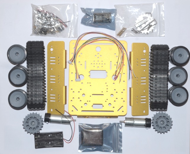
The tank was bought from a Chinese company (SmartArduino). It’s a kit that includes all the components needed for building the tank body. The delivery time of the components is around 4 weeks.
The kit includes:
- Motors + motor cables
- Aluminium body
- Wheels and tracks
- Motor controller (not used in this project)
Spare motor
Considering the long lead time from SmartArduino, a spare motor was bought. The only one available comes with a wheel included.
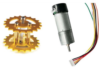
The main characteristics of the motor are listed in the table below.
| Characteristic | Value | Measure |
| Rated voltage (DC) | 9 | [V] |
| Gear ratio | 1/75 | [-] |
| No load speed | 11500 | [rpm] |
| No load current | 180 | [mA] |
| Stall current | 1200 | [mA] |
| Shaft diameter | 4 | [mm] |
The motor is equipped with a hall effect encoder. The encoder has a resolution of 360° (every 360° it provides a growing and a lowering signal).
Arduino board
Arduino is an open-source electronics platform based on easy-to-use hardware and software. Arduino boards are able to read inputs (e.g. a light on a sensor, the signal of a button) and turn it into an output (e.g. activating a motor or turning on an LED) depending on the settings done by the user. You can tell your board what to do by loading a set of instructions to the microcontroller (ATmega 328P) on the board. This is done by using the Arduino programming language and the Arduino Software (IDE).
Documentation is available on Arduino website (https://www.arduino.cc/) and on the web (see YouTube tutorials).
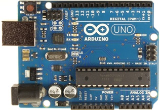
Arduino project created different boards. For this project Arduino UNO board was used, but most of Arduino boards should work.
Arduino board has various ports:
- Digital ports (from 2 to 13 – see Figure 4.5): they are divided in 2 different categories:
- nly digital (2, 4, 7, 8, 12, 13 in Figure 4.5): they can read a digital input and create a digital output
- Digital + PWM (3, 5, 6, 9, 10, 11 in Figure 4.5): they can read a digital input, create a digital output, and create a PMW (pulse width modulation) output
- Analog In ports: they can read an analog input
- Power ports: they include:
- GND ports: they connect the ground to Arduino board
- 5V: it provides a voltage of 5 volts
- 3.3V: it provides a voltage of 3.3 volts
Motor drive board
The motor drive board (also simply called motor controller) is a board which responds to the following functions:
- Receives signals from the Arduino board
- Receives power from the power supply
- Based on the Arduino signals, provides the motors with a defined voltage
The board acts as a “middle interface” between the Arduino and the motor. This is because the motors need to be supplied by an amount of current that Arduino cannot handle. So Arduino provides the signal, while the motor drive board “joins” the signal with the power.
The board can accept a maximum power of 600 mA per channel.

The main component of the board is the chip L293D (from ST Microelectronics). A datasheet can be downloaded from this link: https://www.arduino.cc/documents/datasheets/H-bridge_motor_driver.PDF
The motor drive board includes some other components (that will not be described here), but its main purpose is to allow the user to have a physical connection to the L293D chip.
The chip includes a double H bridge, which is a standard way of controlling DC motors. Thanks to the dual H bridge, this chip can control 2 motors at the same time. The L293D has 16 ports, which are connected to the motor drive shield jumpers. The connections are shown in Figure 4.7.
NOTE: the connections shown in the image show the connections that are internal to the board. The image purpose is to help the reader understand how the board works.
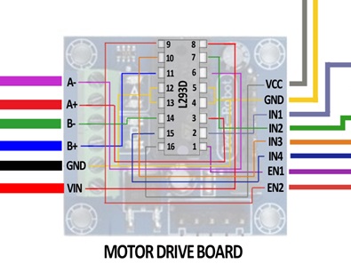
The meaning of the symbols of the figure is explained in the following table.
| Board jumper name | Chip pin # | Voltage [V] | Input/
output |
Function |
| A+ | 3 | 0 to 9 | Output | Provides power connection to motor A. The combination of pins A+ and A- defines motor A speed and direction (e.g. A+ 9V, A- 0V à Rotation in one direction at max speed; A+ 0V, A- 4.5V à Rotation in opposite direction at half speed). |
| A- | 6 | 0 to 9 | Output | |
| B+ | 11 | 0 to 9 | Output | Provides power connection to motor B. The combination of pins B+ and B- defines motor B speed and direction (e.g. B+ 9V, B- 0V à Rotation in one direction at max speed; B+ 0V, B- 4.5V à Rotation in opposite direction at half speed). |
| B- | 14 | 0 to 9 | Output | |
| GND | 4
5 12 13 |
0 | - | Provides common ground for the board. Needs to be connected to Arduino ground and power supply ground. |
| VIN | 8 | 9 | Input | Provides power supply for the motors. |
| VCC | 16 | 5 | Input | Provides power supply for the motor drive board. |
| IN1 | 2 | 0 or 5 | Input | IN1 and IN2 combination defines how the H bridge is connected to the power supply, which influences motor A direction. If IN1 is 5V and IN2 is 0V, motor A will go in one direction. If IN1 is 0V and IN2 is 5V, the motor will go in the opposite direction. |
| IN2 | 7 | 0 or 5 | Input | |
| IN3 | 10 | 0 or 5 | Input | IN3 and IN4 combination defines how the H bridge is connected to the power supply, which influences motor B direction. If IN3 is 5V and IN4 is 0V, motor B will go in one direction. If IN3 is 0V and IN4 is 5V, the motor will go in the opposite direction. |
| IN4 | 15 | 0 or 5 | Input | |
| EN1 | 1 | 0 to 5 | Input | Defines the activation of motor A using a PWM signal. If EN1 is 0V, motor A won’t rotate. If EN1 is 5V, the motor will rotate at full speed. If EN1 is 2.5V, the motor will rotate at half speed. |
| EN2 | 9 | 0 to 5 | Input | Defines the activation of motor B using a PWM signal. If EN2 is 0V, motor B won’t rotate. If EN2 is 5V, the motor will rotate at full speed. If EN2 is 2.5V, the motor will rotate at half speed. |
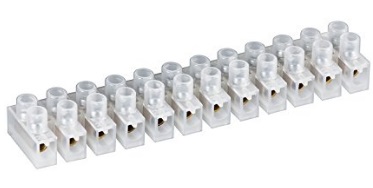
Terminal strip connector
This is an easy way of connecting two cables. It is an alternative to brass welding. The cables are inserted in the two sides of the jumper and clamped with the integrated screws. This guarantees electrical continuity between the two cables.
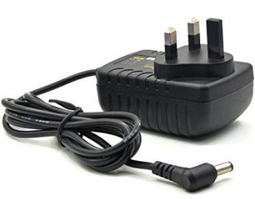
Power supply
The selected power supply provides a voltage of 9V (required from the motor) and a maximum current of 3A. This is higher than the maximum current accepted by the motor controller (2 x 500 mA = 1 A).
The terminal of the power supply was cut to insert the two wires directly into the motor controller.
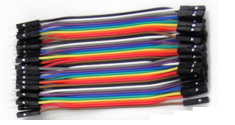
Jumper connectors
They are an easy way of connecting boards. They can be used, for example, to connect Arduino board to the Motor drive board. They can only accept a low current, so they must only be used for providing signal (not power).
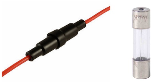
Fuses
A fuse is an electrical safety device that provides overcurrent protection of an electrical circuit. Its essential component is a metal wire that melts when too much current flows through it, thereby interrupting the current. It is a sacrificial device and once a fuse has operated it must be replaced. The fuse is contained inside the fuse holder. The tank uses 500 mA fuses, which provide protection to the Motor drive board (whose maximum current is 600 mA per channel).
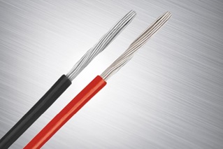
Cable (20 AWG)
A 20 AWG cable is able to transfer a current of 1.5A, so it’s right for transferring current (and power) between the motor drive board and the motors.
WIRING
This chapter describes how the previously described components are wired. All the different wiring steps will be shown at first.
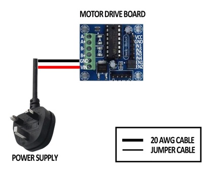
Power supply
Power supply cord is connected as follows:
- Ground cable (black) is connected to GND port
- Power cable (red) is connected to VIN port
Motor drive board to motor
Motor drive board is connected to the motors using the 20 AWG cables. Fuses are inserted to guarantee the safety of the motor drive board.

The connection to the motor pins needs to be done using the positions shown in the following image.

Arduino to Motor drive board
The motor drive board is connected with the Arduino using the Jumper cables. Each cable transfers a signal from the Arduino to the Drive board.
For example, if Arduino pin number 3 goes high, the port EN1 of the board is high. This enables the activation of the motor 1 (see chapter "Motor drive board").

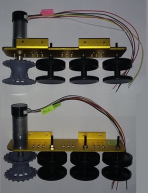
Sensors power + sensor signal
The speed sensors of the two motors are powered by the Arduino 5V power supply (see grey and yellow lines in the following image). The same supply also powers the motor drive board chip. This is possible because the sensors need a very small current to be powered.
The signals from the two sensors are returned back to the Arduino with 2 single cables (see black and blue lines in the following image).
Each sensor also provides a second signal (see light blue and green lines in the following image). These signals could detect the direction of the motors, but are not connected for this application.

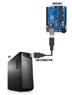
Arduino to PC
Arduino is connected to the PC using the USB connector that is provided in the package. This connection provides:
- The 5V power supply to the Arduino
- The signals between the Arduino and the PC (serial communication)
Overall tank connections
The combination of the connections described in the previous chapters is shown here.

TANK SUPPORT
The structure which supports the tank was built using the following components:
- Plasterboard (available at Homebase)
- Wood bar
- Black tape
- Wide head steel nails
- 5 mm wood dowel

The following tools are suggested:
- Screwdriver
- Jigsaw
Manufacturing and assembly drawings are shown in appendix.
The approach to construction should be as follows:
- Cut the plasterboard to length following the components’ drawings
- Cut the wood bar to length following the components’ drawings
- Drill the holes in the plasterboard
- Drill the holes in the feet using the holes in the plasterboard as a reference
- Apply some tape over the holes in the plasterboard to increase strength
- Assemble the components using nails and dowels
- Position the three blocks close to each other


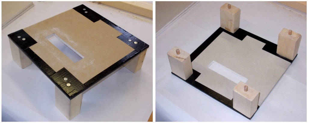

A support for the tank has been created and screwed to the tank bottom panel, as shown in the following figure. The height of this support should be adjusted to keep the tank as close as possible to the tank top panel. No drawings are available for this support.

SOFTWARE
The software for controlling the tank movement is divided into two programming languages:
- Matlab: controls the events which decide when a stimulus should be performed, including:
- Stimulus onset
- Stimulus speed
- Stimulus direction
- Arduino: following the indications given by Matlab program, controls the movements that the motors need to follow during a single stimulation trial. This is done by directly controlling the motor drive board status.
The two programs communicate through a serial communication, which is performed used the USB cable that connects Arduino to the PC. The Arduino then communicates with the Motor drive board for the motor activation using simple 0 to 5V signals. A scheme of the software workflow is shown below.

After the start, an handshake procedure is performed to verify the communication between Matlab and Arduino. Matlab then sends a series of command to Arduino defining the settings of the next stimulus (speed, direction and motor activation). Arduino receives the signals and delivers them to the motor drive board, which activates the motors with the required settings.
While the motors are running, the signals from the encoder are passed to Arduino, which elaborates them and send the time and position readings back to Matlab. This procedure runs continuously while the motors are running.
When the running time has elapsed, Arduino stops the motors and sends a stop signal to Matlab. If Matlab requires a new run to be executed, the procedure is re-started. Otherwise the software stops and waits for a new start indication from the user.
The software for the activation of the tank is recorded and described in the appendix.
APPENDIX - CONSTRUCTION DRAWINGS


APPENDIX - ARDUINO SOFTWARE
Main program
Arduino software is normally divided in 3 main parts:
- Definition of constants and variables: It’s the first part of the code, where variables and constants are defined and initialised. This part is only run once, as soon as Arduino is powered or reset.
- Setup: It contains a series of commands (can also include loops) that only run once, as soon as Arduino is powered or reset. It also includes the initialisation of Arduino ports.
- Loop: This part is run as soon as the previous are completed. The loop code continuously run when Arduino is on (as soon as the code execution is completed it starts back again from the beginning). The loop contains the code that is programmed to react to the stimuli that Arduino receives (e.g. signals from the pc or from sensors).
Definition of constraints
The constants initialised in this block define:
- All the constants that are related to a characteristic of a component (e.g. encoder) or to a wiring (e.g. Arduino connections)
- All the values that will influence the execution of the tank run
They include:
- Setting of motors motion profiles (time and voltage)
- Corrections to compensate the direction of the motors (the same voltage applied to the motor creates different speeds depending on the motor direction – the correction changes the voltage of one direction to compensate this difference)
- Arduino pins settings
- Encoder settings (they depend on its construction characteristics)

//------------------------- INTRODUCTION -----------------------------
//Commands
// a = Motor A forward set
// b = Motor A backwards set
// c = Motor B forward set
// d = Motor B backwards set
// p = Motor A high speed set
// q = Motor A medium speed set
// r = Motor A low speed set
// s = Motor B high speed set
// t = Motor B medium speed set
// u = Motor B low speed set
// e = Motor A start
// f = Motor B start
// g = Motor A & B start

//------------------------- CONSTANTS -----------------------------
//Stimulus settings
const byte AccVoltageA = 250; 			//Voltage during acceleration and deceleration phase (max 255)
const byte AccVoltageB = 250; 			//Voltage during acceleration and deceleration phase (max 255)

const byte StimVoltageAHigh = 250; 		//Voltage during stimulus phase - high speed (max 255)
const byte StimVoltageBHigh = 250; 		//Voltage during stimulus phase - high speed (max 255)
const byte StimVoltageAMid  = 200; 		//Voltage during stimulus phase - medium speed (max 255)
const byte StimVoltageBMid  = 200; 		//Voltage during stimulus phase - medium speed (max 255)
// low speed not used at the moment in matlab script
const byte StimVoltageALow  = 150; 		//Voltage during stimulus phase - low speed (max 255)
const byte StimVoltageBLow  = 150; 		//Voltage during stimulus phase - low speed (max 255)

const unsigned int StimLengthAHigh  = 500; 	 //Duration of the stimulus [ms] (includes acceleration and braking phases) - high speed
const unsigned int StimLengthAMid   = 500;   //Duration of the stimulus [ms] (includes acceleration and braking phases) - medium speed
const unsigned int StimLengthALow   = 500;   //Duration of the stimulus [ms] (includes acceleration and braking phases) - low speed
const unsigned int StimLengthBHigh  = 500;   //Duration of the stimulus [ms] (includes acceleration and braking phases) - high speed
const unsigned int StimLengthBMid   = 500;   //Duration of the stimulus [ms] (includes acceleration and braking phases) - medium speed
const unsigned int StimLengthBLow   = 500;   //Duration of the stimulus [ms] (includes acceleration and braking phases) - low speed

const unsigned int AccLength = 75; 		//Duration of acceleration [ms]
const unsigned int BrakingLength = 250; //Duration of braking [ms]

//Motor settings
const float DirectionCorrectionAHigh  = 1.0; //Direction 0 = direction 1 * DirectionCorrection
const float DirectionCorrectionAMid   = 1.0; //Direction 0 = direction 1 * DirectionCorrection
const float DirectionCorrectionALow   = 1.0; //Direction 0 = direction 1 * DirectionCorrection
const float DirectionCorrectionBHigh  = 1.0; //Direction 1 = direction 0 * DirectionCorrection
const float DirectionCorrectionBMid   = 1.0; //Direction 1 = direction 0 * DirectionCorrection
const float DirectionCorrectionBLow   = 1.0; //Direction 1 = direction 0 * DirectionCorrection


//Arduino pins
const byte EnA = 3 ;  	//MotA enable
const byte EnB = 6 ;  	//MotB enable
const byte InA1 = 2 ; 	//MotA forward
const byte InA2 = 7 ; 	//MotA backwards
const byte InB1 = 4 ; 	//MotB forward
const byte InB2 = 8 ; 	//MotB backwards
const byte EncodA = 12; //Encoder A input
const byte EncodB = 13; //Encoder B input

//Encoder settings
const byte SpeedReadingFrequency = 1; 		//Number of ms between encoder readings
const float SpeedOutputFrequency = 20.00; 	//Number of ms between encoder speed calculation
const float EndCommand = -1;				//Command sent to Matlab to show the end of the run
Definition of variables
This part of the program includes the definition of the variables that are going to be used in the Setup or the Loop blocks. These variables are mostly used to evaluate the current status of the motor and the stimulus.
//------------------------- VARIABLES -----------------------------
//Communication settings
char rxChar = 0; //Variable for receiving commands from Matlab

//Motor status
boolean MotAStatus = false;		//Status of motorA (active or not active)
boolean MotBStatus = false;		//Status of motorB (active or not active)
unsigned long StimulusTime;		//Defines when the current stimulus was done (uses Arduino time system)
unsigned long EncoderTime;		//Defines when last encoder reading was done (uses Arduino time system)
unsigned long EncoderOutputTime;//Defines when last speed output was done (uses Arduino time system)
unsigned long CurrentTime;		//Defines current cycle time (uses Arduino time system)
double VoltageA = 0;			//Defines the voltage applied to motorA
double VoltageB = 0;			//Defines the voltage applied to motorB
boolean MotADirection = false; 	//Defines the rotation direction of motorA. In Matlab: False = 0, True = 1
boolean MotBDirection = false; 	//Defines the rotation direction of motorB. In Matlab: False = 0, True = 1
byte SetStimVoltageA;           //Defines stimulation voltage on motorA depending on the speed setting
byte SetStimVoltageB;           //Defines stimulation voltage on motorB depending on the speed setting
unsigned int StimLengthA;        //Records the stimulus length depending on the speed chosen for the motor
unsigned int StimLengthB;        //Records the stimulus length depending on the speed chosen for the motor
float DirectionCorrectionA;      //Records the direction correction depending on the speed chosen for the motor
float DirectionCorrectionB;      //Records the direction correction depending on the speed chosen for the motor

//Encoder status
byte EncodStatusA = 0;		//Saves the status of the encoder of motorA
byte EncodStatusB = 0;		//Saves the status of the encoder of motorB
byte EncodStatusAPrev = 0;	//Saves the previous status of encoderA
byte EncodStatusBPrev = 0;	//Saves the previous status of encoderB
float EncoderCounterA = 0;	//Counts the number of rotations of encoderA
float EncoderCounterB = 0;	//Counts the number of rotations of encoderB
float EncoderTotalA = 0;
float EncoderTotalB = 0;
double SpeedA = 0;			//Stores the read speed of motorA
double SpeedB = 0;			//Stores the read speed of motorA
Setup
This part of the program executes:
- The initial handshake between Arduino and Matlab (see description in chapter 2.2). The program doesn’t proceed until the handshake is completed.
- The setting of Arduino pins. This assigns a variable to each pin and allows the variable to control the pin status directly.
- The initialisation of the time counters. This will allow to execute the motors activation depending on the time passed from the start of the stimulus.
//------------------------- SETUP -----------------------------
void setup()
{
  // Open serial port, sends the character "a" to Matlab and wait for Matlab to send the same character back (handshake)
  Serial.begin(9600);
  Serial.println('a');
  char a = 'b';
  while (a != 'a')
  {
    a = Serial.read();
  }

  //Arduino pins setting
  pinMode(EnA,OUTPUT);
  pinMode(EnB,OUTPUT);
  pinMode(InA1,OUTPUT);
  pinMode(InA2,OUTPUT);
  pinMode(InB1,OUTPUT);
  pinMode(InB2,OUTPUT);

  //Initialise time counter
  CurrentTime = millis();
  StimulusTime = CurrentTime;
  EncoderTime = CurrentTime;
  EncoderOutputTime = CurrentTime;
Loop
This part of the program receives commands from Matlab and executes the activation of the motors depending on the commands. These are the main parts of the program:
- Receive motor settings from Matlab through serial communication and set Arduino ports depending on the commands
- Receive motor start command from Matlab through serial communication
- Activate the motors and leave them ON for the duration of a single run following the defined motion profile
- While the motors are active, send time and motor position data to Matlab through serial communication
- When the single run is completed send Matlab an “end” command through serial communication
- Wait for the new start command
//------------------------- LOOP -----------------------------
void loop()
{
  //Update current time
  CurrentTime = millis();

  //Read serial status
  if (Serial.available() >0){          // Check receive buffer.
    rxChar = Serial.read();            // Save character received.

  //If command of motors activation is  active, run the routine
      if((MotAStatus == false)&&(MotBStatus == false)){

      //Motors settings depending on serial read
      switch (rxChar) {

        //Mot A forward setting
        case 'a':
          MotADirection = true;
          digitalWrite(InA2,LOW) ;
          digitalWrite(InA1,HIGH) ;
          break;

        //Mot A backwards setting
        case 'b':
          MotADirection = false;
          digitalWrite(InA1,LOW) ;
          digitalWrite(InA2,HIGH) ;
          break;

        //Mot B forward setting
        case 'c':
          MotBDirection = true;
          digitalWrite(InB2,LOW);
          digitalWrite(InB1,HIGH);
          break;

        //Mot B backwards setting
        case 'd':
          MotBDirection = false;
          digitalWrite(InB1,LOW);
          digitalWrite(InB2,HIGH);
          break;

        //MotA Speed setting
        case 'p':
          SetStimVoltageA = StimVoltageAHigh;
          StimLengthA = StimLengthAHigh;
          DirectionCorrectionA = DirectionCorrectionAHigh;
          break;

        //MotA Speed setting
        case 'q':
          SetStimVoltageA = StimVoltageAMid;
          StimLengthA = StimLengthAMid;
          DirectionCorrectionA = DirectionCorrectionAMid;
          break;

        //MotA Speed setting
        case 'r':
          SetStimVoltageA = StimVoltageALow;
          StimLengthA = StimLengthALow;
          DirectionCorrectionA = DirectionCorrectionALow;
          break;

        //MotB Speed setting
        case 's':
          SetStimVoltageB = StimVoltageBHigh;
          StimLengthB = StimLengthBHigh;
          DirectionCorrectionB = DirectionCorrectionBHigh;
          break;

        //MotB Speed setting
        case 't':
          SetStimVoltageB = StimVoltageBMid;
          StimLengthB = StimLengthBMid;
          DirectionCorrectionB = DirectionCorrectionBMid;
          break;

        //MotB Speed setting
        case 'u':
          SetStimVoltageB = StimVoltageBLow;
          StimLengthB = StimLengthBLow;
          DirectionCorrectionB = DirectionCorrectionBLow;
          break;

        //MotA activation setting
        case 'e':
          MotAStatus = true;
          StimulusTime = CurrentTime;
          EncoderTime = CurrentTime - SpeedReadingFrequency - 1;
          EncoderOutputTime = CurrentTime - SpeedOutputFrequency - 1;
          break;

        //MotB activation setting
        case 'f':
          MotBStatus = true;
          StimulusTime = CurrentTime;
          EncoderTime = CurrentTime - SpeedReadingFrequency - 1;
          EncoderOutputTime = CurrentTime - SpeedOutputFrequency - 1;
          break;

        //MotA & MotB activation setting
        case 'g':
          MotAStatus = true;
          MotBStatus = true;
          StimulusTime = CurrentTime;
          EncoderTime = CurrentTime - SpeedReadingFrequency - 1;
          EncoderOutputTime = CurrentTime - SpeedOutputFrequency - 1;
          break;

        //No activation
        case 'h':
          MotAStatus = false;
          MotBStatus = false;
          break;
      }
    }
  }

  //If command of motors activation is  active, run the routine
  if((MotAStatus == true)||(MotBStatus == true)){

    //Check if the stimulus still has to run
    if ((CurrentTime <= (StimulusTime + max(StimLengthA,StimLengthB) + 10))){

      //Speed reading (see http://www.hobbytronics.co.uk/arduino-tutorial6-rotary-encoder)
      if (CurrentTime >= (EncoderTime + SpeedReadingFrequency)){

        //Count revolution of motor A
        EncodStatusA = digitalRead(EncodA);
        if((!EncodStatusA) == (EncodStatusAPrev)){
          EncoderCounterA = EncoderCounterA + 0.5;
          EncodStatusAPrev = EncodStatusA    ;
        }

        //Count revolution of motor B
        EncodStatusB = digitalRead(EncodB);
        if((!EncodStatusB) == (EncodStatusBPrev)){
          EncoderCounterB = EncoderCounterB + 0.5;
          EncodStatusBPrev = EncodStatusB;
        }

        //After reading the revolution, restart encoder time
        EncoderTime = CurrentTime;
      }

      //Computes A and B speed
      if (CurrentTime >= (EncoderOutputTime + SpeedOutputFrequency)) {

        //Send computed values to Matlab through serial
        Serial.println(CurrentTime - StimulusTime);
        Serial.println(EncoderCounterA);
        Serial.println(EncoderCounterB);

        EncoderOutputTime = CurrentTime;

        //MOTOR A
        //Acceleration phase
        if (CurrentTime <= StimulusTime + AccLength){
          VoltageA = AccVoltageA;
        }

        //Stimulus phase
        if ((CurrentTime > StimulusTime + AccLength) && (CurrentTime <= StimulusTime + StimLengthA - BrakingLength)){
          if (MotADirection == false) {
            VoltageA = SetStimVoltageA * DirectionCorrectionA;
          }
          else {
            VoltageA = SetStimVoltageA;
          }
        }

        //Braking phase
        else if ((CurrentTime > StimulusTime + StimLengthA - BrakingLength) && (CurrentTime <= StimulusTime + StimLengthA)){
          VoltageA = AccVoltageA;
          digitalWrite(InA1,LOW) ;
          digitalWrite(InA2,LOW) ;
        }

        //After stimulus phase (to allow speed reading in case stimulus is longer than expected)
        else {
          VoltageA = 0;
        }

        //MOTOR B
        //Acceleration phase
        if (CurrentTime <= StimulusTime + AccLength){
          VoltageB = AccVoltageB;
        }

        //Stimulus phase
        if ((CurrentTime > StimulusTime + AccLength) && (CurrentTime <= StimulusTime + StimLengthB - BrakingLength)){
          if (MotBDirection == false) {
            VoltageB = SetStimVoltageB;
          }
          else {
            VoltageB = SetStimVoltageB * DirectionCorrectionB;
            //B is corrected differently from A because they react differently to the direction correction. This allows to
            //always use a correction that is lower than 1 (if using a higher correction you would have not correction at
            //all if the base voltage was already 255, which is the maximum)
          }
        }

        //Braking phase
        else if ((CurrentTime > StimulusTime + StimLengthB - BrakingLength) && (CurrentTime <= StimulusTime + StimLengthB)){
          VoltageB = AccVoltageB;
          digitalWrite(InB1,LOW) ;
          digitalWrite(InB2,LOW) ;
        }

        //After stimulus phase (to allow speed reading in case stimulus is longer than expected)
        else {
          VoltageB = 0;
        }


    	  //Verify that voltage is not too high
    	  if(VoltageA > 255){
    	    VoltageA = 255;
    	  }
    	  if(VoltageB > 255){
    	    VoltageB = 255;
    	  }

        //Update motor speed
        if(MotAStatus == true){
          analogWrite(EnA,VoltageA);
        }
        if(MotBStatus == true){
          analogWrite(EnB,VoltageB);
        }
      }
    }

  //After the end of the stimulus zero all the motors and send end signal to Matlab
    else {
      //Reset all the motors
      analogWrite(EnA,0);
      analogWrite(EnB,0);
      digitalWrite(InA1,LOW) ;
      digitalWrite(InA2,LOW) ;
      digitalWrite(InB1,LOW) ;
      digitalWrite(InB2,LOW) ;
      MotAStatus = false;
      MotBStatus = false;

    //Send end command to Matlab
      Serial.println(EndCommand);

      //Reset encoder counter
      //EncoderTotalA = 0;
      //EncoderTotalB = 0;
    EncoderCounterA = 0;
    EncoderCounterB = 0;
    }
  }
}